

Plumbing systems are easier to coordinate, review, fabricate, and install when their routes are communicated in a clear three-dimensional drawing. Endeion prepares plumbing isometric drawings that show how water, sanitary, waste, vent, storm, and equipment connection systems relate across floors, elevations, and building zones. The drawings can support plumbing contractors, MEP consultants, general contractors, residential builders, fabricators, and project teams that need more clarity than a conventional floor plan can provide.
Our team develops each plumbing isometric drawing from the approved project information supplied by the client. Depending on the scope, inputs may include plumbing plans, riser diagrams, BIM models, CAD files, PDFs, specifications, equipment schedules, redlines, and coordination decisions. The resulting documentation can help teams understand pipe routing, connections, elevations, slopes, sizes, fittings, and system relationships before or during construction.
Endeion provides drafting, BIM modeling, coordination, and documentation support. Plumbing engineering calculations, code decisions, design approval, professional stamping, and engineer-of-record responsibilities remain with the client or the appointed licensed professional unless they are expressly included through an appropriate agreement.
What Is a Plumbing Isometric Drawing?
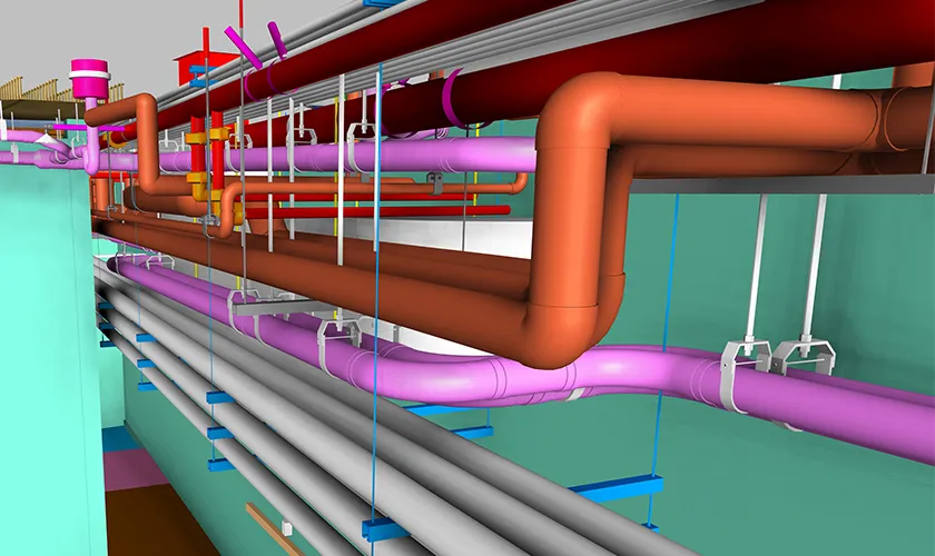
A plumbing isometric drawing is a technical representation that shows a piping system in a three-dimensional style while remaining on a two-dimensional sheet. Horizontal runs are usually represented along angled axes, while vertical stacks and risers remain vertical. This makes it easier to understand how pipes move through floors, walls, shafts, ceilings, and equipment areas.
An isometric plumbing drawing can communicate relationships that are difficult to interpret from a plan alone. It may show fixture connections, branch lines, stacks, vents, pipe sizes, fittings, slopes, elevations, valves, cleanouts, equipment connections, and changes in direction. The exact content depends on the project’s purpose, client standards, and approved design information.
Plumbing Isometric Drawings Versus Plans and Riser Diagrams
Plumbing Isometric Drawings Versus Plans and Riser Diagrams
| Document Type | Primary View | Typical Use |
|---|---|---|
| Plumbing plan | Top or floor-plan view | Shows routing and fixture locations on each level. |
| Plumbing riser diagram | Simplified vertical system diagram | Communicates system relationships between levels, stacks, branches, and major equipment. |
| Plumbing isometric drawing | Three-dimensional angled representation | Clarifies routing, elevations, fittings, connections, offsets, and installation relationships. |
| Coordinated shop drawing | Detailed plan, section, elevation, or model-derived view | Supports trade coordination, installation planning, reviews, and field communication. |
Plumbing Isometric Drawing Services, We Provide
Endeion structures the drawing package around the system, project phase, and intended use. A small residential assignment may require a limited set of domestic water and sanitary isometrics, while a commercial or institutional project may require separate drawings for multiple zones, risers, plant connections, and coordinated service areas.
Domestic and Potable Water Isometrics
We prepare isometric views for cold-water, hot-water, recirculation, and project-specific supply systems based on approved plans and schedules. Drawings may identify pipe sizes, valves, fixtures, equipment connections, branches, risers, and changes in elevation where this information is included in the source documents or agreed coordination model.
Sanitary, Waste, and Vent Isometrics
Sanitary and vent isometrics can show stacks, branches, fixture connections, cleanouts, vents, slopes, fittings, and transitions between building levels. These drawings help teams read the relationship between drainage and vent systems without relying only on separate floor plans and schematic risers.
Storm and Roof Drainage Isometrics
For projects with roof drains, overflow systems, leaders, vertical conductors, and storm connections, Endeion can prepare isometric drawings that organize the approved drainage routes and connection points. Scope and annotations are coordinated with the available design and project requirements.
Equipment and Specialty Plumbing Connections
Where the project documents provide sufficient information, isometrics may cover pumps, water heaters, storage tanks, treatment equipment, fixtures, laboratory or healthcare connections, and other plumbing-related equipment. Required clearances, access zones, and connection data should be confirmed through the project team and applicable design documents.
Residential Plumbing Isometric Drawing Services
A residential plumbing isometric drawing can help home builders, plumbing contractors, designers, and reviewers understand water, waste, and vent routing for single-family homes, townhouses, apartments, and multi-unit residential buildings. Depending on the project, the package may include unit layouts, stacked services, domestic water branches, sanitary stacks, vent routing, and connections to building mains. Repeated unit types can be organized carefully so that drawing references remain clear across floors and building zones.
Renovation and As-Built Plumbing Isometrics
Renovation work often combines incomplete legacy drawings with surveys, redlines, point clouds, photographs, or field-verified information. Endeion can prepare updated isometric documentation from client-provided records and approved markups. When the assignment involves existing conditions, the drawing status, source reliability, field verification responsibility, and level of certainty should be stated clearly.
Information Commonly Shown on Isometric Plumbing Drawings
The drawing content should be established before production begins. Adding unnecessary information can make a sheet difficult to read, while omitting critical dimensions or identifiers can reduce its value in coordination and construction. Depending on the approved scope, an isometric drawing for plumbing may include:
- Pipe sizes, service types, and system abbreviations
- Vertical stacks, risers, horizontal branches, and connection points
- Fittings, offsets, changes in direction, and transitions
- Fixture, equipment, valve, cleanout, and drain references
- Pipe elevations, invert levels, slopes, or level changes when supplied or approved
- Floor, grid, room, zone, shaft, or riser identifiers
- Insulation, material, specification, or system notes when required
- Cross-references to plans, sections, details, schedules, and approved design documents
- Revision notes, drawing status, and project-specific legends
Not every item belongs to every drawing. Endeion develops the sheet content according to the intended review, coordination, fabrication, installation, record, or submission purpose.
Our Plumbing Isometric Drawing Process
1. Scope and Input Review
We review the project type, plumbing systems, available files, drawing standards, required software version, sheet requirements, intended use, delivery schedule, and revision process. Missing or conflicting information is identified for clarification before detailed drafting proceeds.
2. Drawing and Model Setup
The team establishes file organization, coordinates, levels, views, naming conventions, symbols, line styles, title blocks, and reference information. When the isometrics are model-derived, the relevant plumbing model content is checked for completeness and alignment with the approved project inputs.
3. System Tracing and Route Development
Approved plumbing routes are translated into clear isometric views. The drawing is organized to show stacks, branches, fixtures, equipment, offsets, fittings, and transitions without creating unnecessary visual congestion.
4. Annotation and Cross-Referencing
Pipe sizes, elevations, slopes, tags, system names, notes, connection references, and drawing links are added according to the agreed requirements. Annotations are arranged for readability at the intended sheet scale.
5. Coordination Review
Where coordination is included, the plumbing routing is reviewed against relevant architectural, structural, mechanical, electrical, fire protection, and equipment information. Identified issues are documented or updated according to the agreed approval workflow. Drafting changes are not treated as engineering approvals unless confirmed by the responsible project professional.
6. Quality Control and Revision
Before delivery, the team checks sheet references, system continuity, drawing consistency, annotations, dimensions, levels, tags, file naming, and alignment with the approved source information. Client comments are incorporated through the agreed review cycle.
7. Final Delivery
Final files are organized in the required format, which may include PDF, DWG, RVT, NWC, or another agreed project format. Native files, plotted sheets, revision records, and supporting model views are included only when they form part of the approved scope.
BIM-Supported Plumbing Isometric Drawings
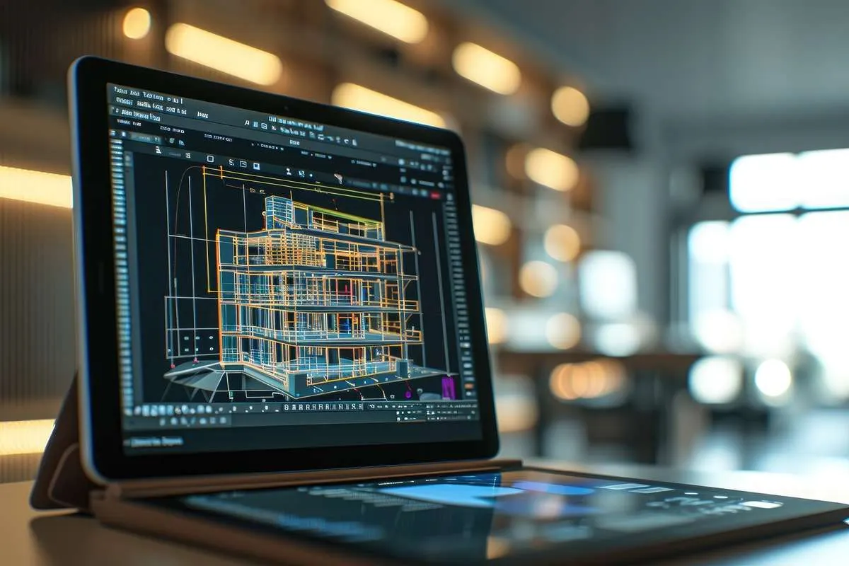
A BIM-based workflow can improve consistency between plumbing plans, sections, schedules, coordinated models, and isometric views. When the underlying model has been developed to the appropriate level and reviewed against the approved design information, model-derived views can reduce repetitive drafting and make revisions easier to track. BIM also helps teams examine how pipes, fixtures, equipment, ceilings, walls, structural elements, and other services interact within congested areas.
BIM does not remove the need for review. Model elements must still carry the correct system assignments, dimensions, elevations, connections, and project data. A clean-looking 3D model may still contain incomplete or inaccurate information, so the output must be checked against the project requirements before it is issued.
Plumbing Isometric Drawing Software and File Workflows
The appropriate plumbing isometric drawing software depends on the project inputs and expected deliverables. Endeion works within established BIM and CAD workflows that can include Autodesk Revit for model-based plumbing systems, AutoCAD for detailed 2D documentation and drawing conversion, and Navisworks for multidisciplinary model review and coordination. Software selection, file versions, export settings, and required deliverables are confirmed during project setup.
The final isometric plumbing drawing may be drafted from approved 2D information or generated from a coordinated model, depending on the required workflow.
Who Uses Plumbing Isometric Drawings?
- Plumbing contractors and subcontractors planning system routing and field installation
- MEP consultants and engineers reviewing system relationships and documentation
- General contractors coordinating plumbing with structure, architecture, HVAC, electrical, and fire protection
- Residential builders organizing repeated units, stacked services, and house plumbing systems
- Fabricators and prefabrication teams developing approved assemblies or pipe sections
- Owners and facility teams documenting existing plumbing systems for renovation or maintenance
- BIM and VDC teams integrating plumbing information into coordinated project models
Benefits of Clear Plumbing Isometric Documentation
Improved System Understanding
Three-dimensional representation makes it easier to understand vertical and horizontal relationships, particularly where several fixtures, stacks, branches, and offsets occur within a compact space.
Better Coordination with Other Disciplines
Isometric views can supplement plans and coordinate models by clarifying where plumbing systems pass through shafts, walls, floors, ceilings, and equipment areas. This supports discussions with architectural, structural, mechanical, electrical, and fire protection teams.
Clearer Field Communication
A well-organized drawing can reduce interpretation gaps by presenting pipe routes, fittings, connections, and level changes in one view. Site teams should still follow approved construction documents, specifications, code requirements, and project instructions.
Support for Material Planning and Prefabrication
When the information is sufficiently developed and approved, isometrics can support quantity review, fitting identification, spool planning, and prefabrication discussions. Material takeoffs, fabrication drawings, and spool drawings are separate deliverables and should be defined independently when required.
More Controlled Revisions
A structured CAD or BIM workflow makes it easier to update drawings when approved routes, sizes, equipment, fixtures, or project conditions change. The revision scope depends on the quality of the updated inputs and the agreed issue-management process.
How to Draw Isometric Plumbing Clearly
People searching for how to draw isometric plumbing often begin with a floor plan and a simplified riser. A professional workflow normally follows these steps:
- Confirm the approved system design, fixture schedule, pipe sizes, materials, code criteria, and project standards.
- Set consistent isometric axes and decide how vertical stacks, horizontal branches, and offsets will be represented.
- Trace the system from its source or connection point through mains, risers, branches, fixtures, and equipment.
- Show fittings, changes in direction, elevations, slopes, and connections without overlapping important information.
- Add system labels, pipe sizes, tags, notes, cleanouts, valves, equipment references, and cross-references.
- Check continuity against plans, risers, BIM models, schedules, specifications, and approved coordination decisions.
- Complete a final drawing review for readability, scale, sheet organization, revision status, and project-specific requirements.
This overview is educational and does not replace plumbing design, code review, hydraulic calculations, engineering approval, or project-specific drafting standards.
What to Check in Isometric Plumbing Drawing Examples
Generic isometric plumbing drawing examples can help explain visual conventions, but they should not be copied directly into a live project. A useful example should have consistent axes, readable routing, clear fixture and stack identification, complete system continuity, appropriate pipe-size notation, visible fittings and offsets, and references that correspond with the related plan or riser. Project teams should rely on approved project information rather than a sample drawing when making construction decisions.
Typical Deliverables of Plumbing Isometric Drawing
| Deliverable | Possible Content | Scope Note |
|---|---|---|
| Plumbing isometric sheets | Water, sanitary, vent, storm, equipment, or project-specific systems | Prepared by system, floor, zone, riser, or package as agreed. |
| Model-derived views | Isometric views generated from an approved plumbing BIM model | Requires suitable model content and project-specific view setup. |
| 2D CAD isometrics | Detailed DWG documentation developed from approved drawings or markups | Native CAD standards and layers are confirmed at setup. |
| Residential plumbing isometrics | House, unit, stack, water, waste, and vent diagrams | Coverage depends on the approved residential design inputs. |
| Renovation or record drawings | Updated isometrics based on surveys, redlines, scans, or field records | Verification status and source limitations must be identified. |
| Supporting schedules or legends | System abbreviations, notes, fixture references, and drawing keys | Included only when required by the drawing package. |
Why Choose Endeion for Plumbing Isometric Drawings?
Integrated MEP BIM and Drawing Experience
Endeion’s broader MEP capabilities include plumbing modeling, MEP coordination, shop drawings, spool drawings, builders’ work drawings, CAD-to-BIM conversion, and as-built documentation. This allows the isometric drawing scope to connect with related modeling or coordination services when the project requires them.
Project-Specific Drawing Standards
We work from the client’s title blocks, symbols, layers, naming conventions, BIM execution requirements, software versions, and submission standards. Where requirements are incomplete, assumptions are documented for review before final production.
Flexible Inputs and Deliverables
Projects may begin with BIM models, CAD drawings, PDFs, risers, sketches, markups, scans, or existing records. The recommended workflow depends on the reliability and completeness of those inputs and the level of output required.
Structured Quality Checks
Our review focuses on drawing continuity, system identifiers, references, dimensions, elevations, slopes, tags, sheet organization, and consistency with the approved source information. Quality control verifies the drafting deliverable; it does not replace design review or professional approval.
Scalable Project Support
Endeion can support a single isometric package, a multi-floor drawing assignment, a residential program, or plumbing documentation within a broader BIM and coordination scope. Resource planning and turnaround are confirmed after reviewing project complexity, inputs, volume, and schedule.
FAQs About Plumbing Isometric Drawings
What is a plumbing isometric drawing?
A plumbing isometric drawing is a technical drawing that represents piping in a three-dimensional angled view on a two-dimensional sheet. It can show vertical stacks, horizontal branches, fixtures, fittings, pipe sizes, slopes, elevations, and equipment connections more clearly than a floor plan alone.
What is the difference between an isometric plumbing drawing and a riser diagram?
A riser diagram generally provides a simplified schematic of vertical system relationships between floors. An isometric drawing plumbing package normally shows more of the actual routing, fittings, offsets, branches, and three-dimensional relationships. Project conventions vary, so the required content should be defined before drafting.
Can Endeion prepare a residential plumbing isometric drawing?
Yes. Endeion can prepare residential plumbing isometrics for single-family, townhouse, apartment, and multi-unit projects from approved plans, risers, models, schedules, and markups. The exact systems, sheet count, level of detail, and review requirements are confirmed during scoping.
What information is needed to create plumbing isometric drawings?
Useful inputs include approved plumbing plans, riser diagrams, BIM or CAD files, fixture and equipment schedules, pipe sizes, system specifications, levels, slopes, elevations, title blocks, drawing standards, coordination decisions, and required output formats. Missing information should be resolved or documented before issue.
Can an isometric drawing for plumbing be created from PDFs or 2D CAD files?
Yes. Isometrics can be drafted from suitable PDFs, CAD plans, risers, sketches, or marked-up drawings. The accuracy and completeness of the output depend on the reliability of the source information. A BIM-based workflow may be recommended when the project also requires model coordination or repeated revisions.
Which plumbing isometric drawing software does Endeion use?
Depending on the project, Endeion can use established Autodesk workflows such as Revit for model-based plumbing documentation, AutoCAD for 2D drafting, and Navisworks for multidisciplinary model review. The software version and final file formats are agreed during project setup.
Are plumbing isometrics the same as spool drawings?
No. Plumbing isometrics communicate system routing and relationships, while spool drawings divide approved piping into defined fabrication and assembly units with more specific production information. If spool drawings are required, they should be scoped separately from general isometric documentation.
Can plumbing isometric drawings be used for permits or approvals?
They may support a submission when required by the authority, client, consultant, or project standard, but acceptance depends on local requirements and the responsible licensed professional. Endeion prepares documentation from approved information and does not guarantee permit approval or replace required engineering review and stamping.
Can Endeion update existing or as-built plumbing isometrics?
Yes. Existing drawings can be updated from reliable redlines, surveys, point clouds, photographs, field records, or client-approved changes. The final drawing should state whether it represents design intent, coordinated routing, record information, or field-verified conditions.
How long does a plumbing isometric drawing project take?
The schedule depends on the number of systems, floors, risers, fixtures, drawing standards, input quality, coordination needs, review cycles, and requested formats. Endeion confirms a delivery plan after reviewing the scope and available project information.
Areas We Serve
- Alabama
- Albany
- Arizona
- Atlanta
- Augusta
- Bakersfield
- Boston
- Brownsville
- Buffalo
- California
- Charlotte
- Chicago
- Cleveland
- Colorado
- Columbia
- Columbus
- Concord
- Connecticut
- Dallas
- Florida
- Georgia
- Hawaii
- Houston
- Illinois
- Indiana
- Kansas
- Kentucky
- Los Angeles
- Louisiana
- Maine
- Maryland
- Massachusetts
- Mississippi
- Missouri
- Montana
- Nebraska
- Nevada
- New Hampshire
- New Mexico
- New York
- North Carolina
- North Dakota
- Ohio
- Oklahoma
- Oregon
- Orlando
- Pennsylvania
- Portland
- Rhode Island
- Seattle
- South Carolina
- Texas
- Vermont
- Virginia
- Washington
- West Virginia
- Wisconsin