



Table of Contents
Before any physical construction begins, a building must first be built on paper, or, more accurately today, in digital models and drawings. Design and construction drawings form the backbone of every successful construction project, serving as a common language that aligns architects, engineers, contractors, and stakeholders. Without these drawings, even the most well-funded projects can face miscommunication, delays, cost overruns, and compliance issues.
Construction drawings translate ideas into actionable instructions. They define dimensions, materials, locations, system layouts, and construction methods, ensuring that every party involved understands what needs to be built and how. From conceptual planning to on-site execution and long-term facility management, construction drawings guide the project at every stage, making them indispensable to modern building practices.
What Are Design and Construction Drawings?
Design and construction drawings are detailed graphical representations that illustrate how a building or infrastructure project will be designed, constructed, and assembled. These drawings combine visual clarity with technical precision to communicate design intent, structural requirements, and system coordination.
Design drawings focus on the conceptual and aesthetic aspects of a building, such as spatial layouts, form, and appearance. Construction drawings, on the other hand, provide the technical depth required for execution, including measurements, material specifications, installation details, and construction sequences. Together, they bridge the gap between vision and reality.
Today, these drawings are typically produced using Computer-Aided Design (CAD) and Building Information Modeling (BIM) tools, allowing for higher accuracy, easier revisions, and better coordination across disciplines.
How Construction Drawings Are Classified
Construction drawings are classified based on their function, discipline, and role within the project lifecycle. Each category serves a distinct purpose, addressing specific aspects of design, structure, systems, or execution. Understanding these classifications helps stakeholders interpret drawings correctly and ensures smoother coordination throughout the construction process.
The primary categories include architectural drawings, structural drawings, MEP drawings, HVAC and fire protection drawings, and execution-specific drawings such as shop and as-built drawings.
Architectural Drawings
Architectural drawings form the foundation of a construction project by defining the building’s layout, appearance, and spatial relationships. These drawings communicate design intent while ensuring that the structure meets functional and regulatory requirements.
Site Plan Drawings
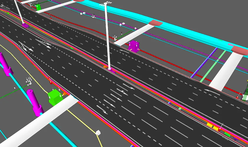
Site plan drawings provide an overall view of the project location, illustrating property boundaries, access roads, utilities, landscaping, setbacks, and surrounding infrastructure. They establish how the building integrates with its environment and site-specific constraints.
Floor Plan Drawings
Floor plan drawings depict horizontal layouts of each level, showing room dimensions, walls, doors, windows, and circulation paths. They are essential for space planning, functional zoning, and coordination with structural, electrical, and plumbing systems.
Elevation Drawings
Elevation drawings represent the exterior faces of a building, highlighting heights, materials, finishes, and architectural features. These drawings help visualize the final appearance and ensure design consistency across all façades and building sides.
Section Drawings
Section drawings provide vertical cut-through views of the building, revealing relationships between floors, ceilings, roofs, walls, and structural components. They clarify construction depth, internal connections, and details not visible in plans or elevations.
Working Drawings
Working drawings are detailed, construction-ready documents used directly on-site by contractors. They include precise dimensions, annotations, material specifications, and installation details required to execute construction accurately and efficiently.
Together, architectural drawings translate creative concepts into buildable designs while setting the framework for all other disciplines.
Structural Drawings
Structural drawings ensure a building’s strength, stability, and safety by defining how loads are transferred through the structure to the ground. Prepared by structural engineers, they address resistance to gravity, wind, seismic, and other environmental forces.
Foundation Drawings
Foundation drawings detail the type, depth, dimensions, and reinforcement of foundations. They illustrate how structural loads are safely distributed to the soil, ensuring stability, durability, and compliance with geotechnical and safety requirements.
Column and Beam Layouts
Column and beam layouts show the positioning, size, and alignment of vertical and horizontal load-bearing elements. These drawings ensure efficient load transfer while coordinating accurately with architectural layouts and floor plans.
Slab Drawings
Slab drawings define slab thickness, reinforcement patterns, support conditions, and openings. They are critical for ensuring floor strength, controlling deflection, and accommodating structural loads imposed by occupancy and equipment.
Reinforcement Drawings
Reinforcement drawings specify the size, spacing, and placement of steel bars within concrete elements. These drawings are essential for achieving structural integrity, crack control, and compliance with engineering design standards.
Together, structural drawings translate engineering calculations into precise construction instructions, ensuring the building performs safely under all expected loads while remaining fully coordinated with architectural and MEP systems.
MEP Drawings (Mechanical, Electrical, and Plumbing)
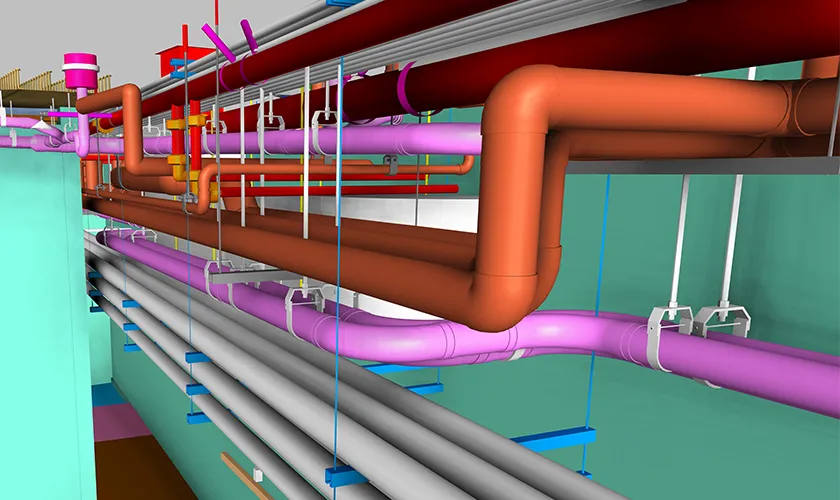
MEP drawings describe the systems that make a building functional and habitable. These drawings require close coordination, as mechanical, electrical, and plumbing systems often share limited space within the structure.
Mechanical Drawings
Mechanical drawings focus on heating, ventilation, and air-conditioning systems, illustrating equipment locations, duct routing, airflow paths, and control strategies. They ensure thermal comfort, indoor air quality, and energy-efficient performance throughout the building.
Electrical Drawings
Electrical drawings depict lighting layouts, power distribution systems, panel boards, wiring routes, grounding, and safety components. These drawings support efficient energy use, proper load balancing, and strict compliance with electrical codes and safety standards.
Plumbing Drawings
Plumbing drawings map water supply lines, drainage systems, fixtures, pipe sizes, and slopes. They ensure reliable water distribution, effective waste removal, and compliance with plumbing codes while coordinating with structural and architectural elements.
MEP shop drawings are essential for avoiding system clashes, optimizing performance, and ensuring long-term operational efficiency.
HVAC and Fire Protection Drawings
HVAC and fire protection drawings focus on occupant comfort and safety; two critical aspects of any building.
HVAC Drawings
HVAC drawings detail heating and cooling systems, ventilation routes, equipment placement, airflow patterns, and control strategies. They ensure proper indoor air quality, thermal comfort, energy efficiency, and coordination with architectural and structural elements.
Fire Protection Drawings
Fire protection drawings outline life-safety systems such as sprinklers, alarms, hydrants, hose reels, and smoke control measures. Developed in strict compliance with fire codes, they are reviewed by authorities to ensure occupant safety and emergency preparedness.
Shop Drawings and As-Built Drawings
While design and construction drawings guide planning, shop drawings and as-built drawings focus on execution and documentation.
Shop Drawings
Shop drawings are prepared by contractors, subcontractors, or manufacturers to provide detailed fabrication and installation instructions. They illustrate dimensions, materials, tolerances, and assembly methods, reflecting actual construction practices rather than conceptual design intent.
As-Built Drawings
As-built drawings document final constructed conditions, capturing all changes made during construction. They show accurate dimensions, locations, and materials, serving as essential references for facility management, maintenance planning, renovations, and future upgrades.
Both drawing types ensure accuracy, accountability, and long-term project value.
Common Mistakes in Construction Drawings and How to Avoid Them
Even minor errors in construction drawings can lead to significant delays, rework, and cost overruns during construction. Identifying common issues early and addressing them systematically is essential for maintaining project efficiency and accuracy.
1. Incomplete or Missing Details
Drawings that lack clear dimensions, material specifications, or construction notes often force contractors to make assumptions on-site. This can result in incorrect installations, rework, and project delays.
How to avoid
Use standardized drawing checklists, peer reviews, and detailed annotations to ensure completeness before issuing drawings.
2. Poor Coordination Between Disciplines
Lack of coordination between architectural, structural, and MEP drawings can cause system clashes, such as ducts intersecting beams or pipes conflicting with electrical conduits.
How to avoid
Conduct interdisciplinary coordination reviews and use BIM-based clash detection to resolve conflicts early in the design phase.
3. Outdated or Uncontrolled Revisions
Using outdated drawings on-site can lead to construction errors and missed updates. Poor version control increases confusion and disrupts workflow continuity.
How to avoid
Implement strict revision control procedures and distribute drawings through centralized digital platforms to ensure teams access only the latest versions.
4. Incorrect Scaling and Measurement Errors
Misinterpreting scales or using incorrectly scaled drawings can result in dimensional inaccuracies and misaligned installations.
How to avoid
Clearly label scales on all drawings, verify printed scales before use, and rely on digital measurement tools when possible.
Conclusion: Why the Right Drawings Define Project Success
Design and construction drawings are far more than technical documents; they are the strategic tools that transform ideas into successful, buildable realities. By clearly defining layouts, structures, systems, and execution methods, these drawings ensure coordination, accuracy, and compliance at every stage of a project.
As construction projects grow in complexity, the importance of precise, well-coordinated drawings continues to rise. Organizations like Endeion support this evolving landscape by delivering reliable design and construction documentation that helps teams build with confidence, clarity, and control.
FAQs
What is the main purpose of construction drawings?
Construction drawings provide detailed visual and technical instructions for building a project, ensuring accurate execution, proper coordination among trades, regulatory compliance, and reduced errors throughout the construction lifecycle.
How are design drawings different from construction drawings?
Design drawings focus on conceptual intent, layout, and aesthetics, while construction drawings translate those concepts into precise technical documents that guide materials, dimensions, installation methods, and on-site execution.
Why are MEP drawings critical in construction projects?
MEP drawings ensure mechanical, electrical, and plumbing systems are accurately coordinated within limited building spaces, helping prevent clashes, improve system performance, and maintain safety, efficiency, and long-term operational reliability.
When are as-built drawings prepared and why are they important?
As-built drawings are prepared after construction completion to document actual site conditions and changes, serving as essential references for facility management, maintenance, renovations, and future expansion projects.

