

• contact@endeion.com
  • 12020 Sunrise Valley Dr, Reston, VA 20191, USA
  • Careers
  • Case Studies
  • Blog
  • Faqs
  • BIM Education
  • Careers
  • Case Studies
  • Blog
  • Faqs
  • BIM Education
Endeion
  • Home
  • BIM Consulting
  • Services
  • Portfolio
  • Sectors
  • About Us
  • Contact
(571) 303-9797
Get A Quote
BIM 3D building model displayed on laptop screen
BIM Services
  • BIM For Infrastructure And Civil
  • MEP BIM / VDC Services
  • BIM Coordination
  • BIM Object Library Creation
  • Quantity Takeoff Services
  • Offshore BIM Team
  • COBie Services
  • BIM Walkthrough
  • Point Cloud To BIM Services
  • Revit Family Creation Services
  • Revit BIM Services
  • BIM For Infrastructure And Civil
  • MEP BIM / VDC Services
  • BIM Coordination
  • BIM Object Library Creation
  • Quantity Takeoff Services
  • Offshore BIM Team
  • COBie Services
  • BIM Walkthrough
  • Point Cloud To BIM Services
  • Revit Family Creation Services
  • Revit BIM Services
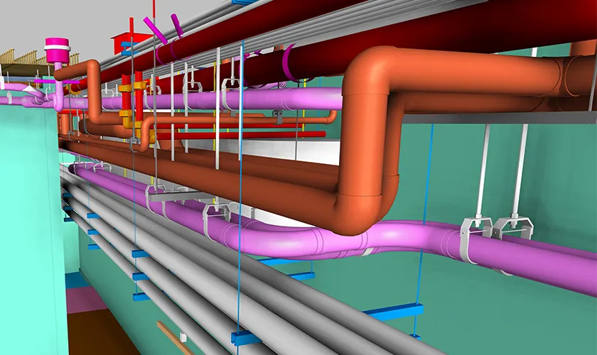
3D BIM model showcasing MEP piping systems in a construction project
MEP Services
  • MEP BIM Modeling
  • CAD to BIM
  • MEP Coordination
  • MEP Shop Drawings
  • MEP 2D Drafting
  • Mechanical Room Modeling
  • Spool Drawings / Digital Prefabrication
  • As Built Drafting
  • Builders Work Drawings
  • Plumbing Isometric Drawing Services
  • MEP BIM Modeling
  • CAD to BIM
  • MEP Coordination
  • MEP Shop Drawings
  • MEP 2D Drafting
  • Mechanical Room Modeling
  • Spool Drawings / Digital Prefabrication
  • As Built Drafting
  • Builders Work Drawings
  • Plumbing Isometric Drawing Services
mechanical-engineering-design-software-computer-screen
Mechanical CAD Services
  • Mechanical 3D Modeling
  • 3D Part Modeling
  • Assembly Modeling
  • Complex Surface Modeling/3D Surfacing
  • Geometric Dimensioning and Tolerancing (GD&T)
  • Mechanical Drafting
  • Product Design
  • Sheet Metal Drawings
  • Bill Of Materials (BOM)
  • Mechanical 3D Modeling
  • 3D Part Modeling
  • Assembly Modeling
  • Complex Surface Modeling/3D Surfacing
  • Geometric Dimensioning and Tolerancing (GD&T)
  • Mechanical Drafting
  • Product Design
  • Sheet Metal Drawings
  • Bill Of Materials (BOM)
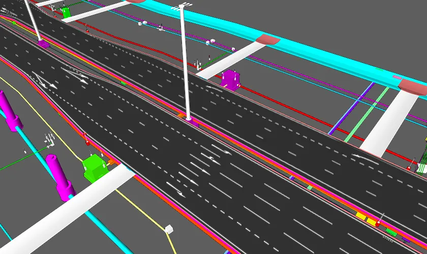
3D BIM model of civil infrastructure with roadways, utilities, and signage
Civil / Infrastructure Services
  • Civil/Infrastructure BIM
  • Clash Detection & Coordination
  • Civil Shop Drawings
  • As-built Documentation
  • Civil/Infrastructure BIM
  • Clash Detection & Coordination
  • Civil Shop Drawings
  • As-built Documentation
  • BIM Model Auditing
  • BIM Implementation
  • BIM Advisory Services
  • BIM Management Services
  • BIM Facility Management Services
  • BIM Template and Content Creation
  • BIM Execution Plan (BEP)
  • BIM Innovation
  • BIM Outsourcing Services
  • BIM Model Auditing
  • BIM Implementation
  • BIM Advisory Services
  • BIM Management Services
  • BIM Facility Management Services
  • BIM Template and Content Creation
  • BIM Execution Plan (BEP)
  • BIM Innovation
  • BIM Outsourcing Services
  • Healthcare
  • Educational
  • Commercial
  • Residential
  • Hotel + Leisure
  • Industrial
  • Infrastructure
  • Product Manufacturing
  • Healthcare
  • Educational
  • Commercial
  • Residential
  • Hotel + Leisure
  • Industrial
  • Infrastructure
  • Product Manufacturing
  • BIM Models
  • Shop Drawings
  • BIM Videos
  • BIM Models
  • Shop Drawings
  • BIM Videos

Understanding Pipe Spools in Fabrication and Assembly

August 21, 2026
  • BIM Technology
  • Construction Technology
  • Industrial & Factory
Understanding Pipe Spools in Fabrication and Assembly

Table of Contents

  • What Are Pipe Spools?
    • What Components Can Be Included in a Piping Spool?
  • Pipe Spooling Versus Traditional Field Fabrication
  • How Spool Boundaries Are Determined
  • What Is Included in a Pipe Spool Drawing?
  • The Pipe Spool Fabrication Process
    • 1. Review Approved Inputs and Release Status
    • 2. Verify Materials and Traceability
    • 3. Cut, Bevel, and Prepare Components
    • 4. Fit Up and Align the Assembly
    • 5. Apply Tack Welds and Recheck Dimensions
    • 6. Complete Welding Under Approved Procedures
    • 7. Perform Heat Treatment or Controlled Cooling When Required
    • 8. Inspect Welds and Dimensions
    • 9. Complete Testing, Cleaning, and Surface Protection
    • 10. Mark, Document, and Release the Spool
    • 11. Pack and Transport for Installation
  • Quality Control and Documentation in Spool Fabrication
  • How BIM Supports Piping Spooling
    • Model Readiness Before Piping Spool Prefabrication
  • Benefits of Pipe Spool Fabrication
  • Where Pipe Spooling Delivers the Most Value
  • Common Pipe Spooling Challenges and How to Address Them
    • Incomplete or Changing Design Information
    • Incorrect Existing-Condition Data
    • Poor Spool Segmentation
    • Trade Coordination Conflicts
    • Fabrication Distortion or Dimensional Drift
    • Traceability Gaps
    • Transport Damage
    • Installation Sequence Problems
    • Disconnected Digital Workflows
  • Best Practices for Successful Piping Spool Fabrication
  • How to Evaluate Prefabrication Spooling Services
  • Pipe Spool Assembly and Field Installation
  • The Future of Pipe Spooling and Digital Prefabrication
  • Conclusion
  • Frequently Asked Questions
    • What is pipe spool fabrication?
    • What is the difference between pipe spooling and piping spool fabrication?
    • What information should a pipe spool drawing include?
    • How are pipe spools sized for transport and installation?
    • Which inspections are used during industrial pipe spool fabrication?
    • Does every piping spool receive a pressure test in the fabrication shop?
    • How does BIM improve piping spooling?
    • What causes pipe spools not to fit in the field?
    • When should a field-fit spool be used?
    • What should be considered when choosing prefabrication spooling services?
    • Can pipe spools be used for both commercial MEP and industrial systems?
    • How early should pipe spooling begin?

Modern industrial, commercial, healthcare, infrastructure, and manufacturing projects depend on piping systems that must fit within increasingly congested spaces. A single line may pass through structural framing, equipment zones, access corridors, electrical pathways, and HVAC systems before it reaches its final connection. When those systems are fabricated mainly in the field, even a small dimensional error or coordination gap can lead to cutting, rewelding, schedule disruption, and avoidable safety exposure.

Pipe spools provide a more controlled approach. Instead of assembling every pipe, fitting, flange, and branch connection at the jobsite, project teams divide the coordinated piping network into manageable prefabricated sections. Each section is detailed, fabricated, inspected, labeled, transported, and installed as a defined assembly. This process, commonly known as pipe spooling, shifts a large portion of the work into a shop or fabrication yard where conditions, equipment, quality procedures, and production sequencing can be managed more consistently.

Effective pipe spool fabrication is not simply off-site welding. It requires accurate design inputs, sensible spool boundaries, fabrication-ready drawings, material control, approved welding procedures, inspection records, transportation planning, and field feedback. When these parts work together, piping spool prefabrication can reduce site congestion, improve installation predictability, and support faster, safer project delivery.

This guide explains what pipe spools are, how piping spool fabrication works, what information a spool drawing should contain, where BIM adds value, and which quality and coordination practices help prevent problems from reaching the field.

What Are Pipe Spools?

A pipe spool is a prefabricated portion of a larger piping system. It normally includes one or more pipe segments together with fittings, flanges, branch connections, reducers, couplings, or other components assembled to an approved design. The completed spool is delivered to the site and connected to adjacent spools, equipment, valves, or field-installed piping.

The term piping spool is often used interchangeably with pipe spool. In practice, both refer to a defined fabrication and installation unit rather than an entire piping line. A spool may be relatively simple, such as a straight section with two flanges, or highly complex, such as a multi-branch assembly serving equipment in a mechanical room or process area.

Pipe spools are used in process plants, power facilities, data centers, hospitals, laboratories, water and wastewater facilities, manufacturing plants, central utility plants, commercial buildings, and infrastructure projects. The exact fabrication requirements depend on the piping service, material, pressure, temperature, governing code, project specification, and owner requirements.

What Components Can Be Included in a Piping Spool?

A spool can contain several component types, provided the assembly remains practical to fabricate, inspect, transport, lift, and install. Typical components include:

  • Pipe in the required nominal size, schedule, wall thickness, material grade, and end preparation.
  • Elbows, tees, reducers, caps, crosses, laterals, and branch fittings that change direction, size, or flow path.
  • Flanges and connection components for bolted, welded, grooved, threaded, or mechanical joints.
  • Welded branch outlets, reinforcement details, specialty fittings, and instrument connections where specified.
  • Valves, strainers, inline devices, and specialty items when the handling plan and project requirements allow shop installation.
  • Temporary shipping braces, lifting points, or protective covers when needed for transport and preservation.
  • Identification tags and traceability markings that connect the physical spool to the drawing, line number, material records, and installation location.

Supports are sometimes attached in the shop, but this depends on the design, support type, coating sequence, transport plan, and whether field adjustment is expected. Items that are sensitive to damage, calibration, contamination, or alignment may be shipped separately even when they appear in the coordinated model.

Pipe Spooling Versus Traditional Field Fabrication

Traditional field fabrication requires crews to measure, cut, fit, weld, and inspect a significant portion of the piping at the construction site. That approach may be appropriate for small modifications, uncertain existing conditions, final tie-ins, or locations where a prefabricated assembly cannot be transported or maneuvered. However, it also places more work in an environment affected by weather, access restrictions, congestion, changing site conditions, and competition with other trades.

Piping spooling moves repeatable and measurable work to a controlled facility. Site work is then focused on receiving, staging, lifting, aligning, connecting, testing, and completing planned field welds or mechanical joints. The goal is not to eliminate field fabrication completely. The goal is to reduce it to the amount that is necessary and strategically planned.

FactorShop-Fabricated SpoolsField FabricationPlanning Implication
Work EnvironmentControlled shop or fabrication yardActive construction siteUse the shop for repeatable work and the field for final connections and conditions that cannot be fixed early.
Dimensional ControlBased on coordinated model and approved drawingsOften depends on site measurement and accessField verification remains essential at tie-ins and existing interfaces.
Quality ManagementCentralized procedures, tooling, and inspection pointsMore variable working conditionsInspection requirements must be defined for both shop and field welds.
ScheduleCan proceed in parallel with site workUsually follows site access and readinessRelease fabrication only when design information is sufficiently stable.
HandlingRequires transport, lifting, and storage planningComponents handled in smaller piecesSpool size and weight must reflect route and equipment limits.

How Spool Boundaries Are Determined

One of the most important decisions in pipe spooling is where to divide a piping system into individual fabrication units. A spool break should be intentional. Dividing a system only by drawing convenience can create assemblies that are difficult to weld, inspect, transport, lift, or install.

A well-planned spool boundary considers the following factors:

  • Transport envelope: The spool must fit on the intended truck, through site gates, inside elevators or hoists, and along the planned delivery route.
  • Weight and center of gravity: The assembly must remain within the safe capacity of shop handling equipment, cranes, forklifts, chain falls, and field lifting devices.
  • Installation access: Crews need enough room to rotate, align, bolt, weld, inspect, and maintain the assembly without interfering with adjacent systems.
  • Shop capability: Spool dimensions and complexity should match available positioners, welding stations, cutting equipment, inspection areas, and storage capacity.
  • Field-weld strategy: Field welds should be placed where access, safety, fit-up tolerance, and inspection are practical.
  • Equipment and tie-in interfaces: Connections to pumps, vessels, skids, existing piping, and vendor equipment often require controlled field verification.
  • Coating, lining, insulation, and testing: The spool layout should support any required surface preparation, heat treatment, cleaning, coating, or examination sequence.
  • Construction sequence: Spools should be released and installed in an order that supports access, rack loading, equipment placement, and work by other trades.

For congested projects, spool segmentation is best completed collaboratively by the BIM or detailing team, fabrication personnel, field supervisors, quality representatives, logistics teams, and the responsible engineer or contractor. That shared review prevents a digitally correct spool from becoming a physically impractical one.

What Is Included in a Pipe Spool Drawing?

A spool drawing converts coordinated design information into instructions that a fabrication shop and installation crew can follow. It is usually derived from an approved model, piping isometric, or coordinated layout, then supplemented with project-specific fabrication and quality information.

The exact format varies, but a fabrication-ready drawing commonly includes:

  • Spool number, line number, service, area, system, drawing revision, and release status.
  • An isometric or orthographic representation with clear orientation and connection references.
  • Centerline dimensions, cut lengths, elevations, slopes, offsets, angles, and critical overall dimensions.
  • Pipe size, schedule, material specification, component descriptions, ratings, and end preparations.
  • Bill of materials or material takeoff with item numbers and quantities.
  • Weld numbers, weld type, shop-weld and field-weld distinctions, and weld map references.
  • Flange orientation, bolt-hole orientation, branch rotation, valve orientation, and equipment connection requirements.
  • Notes for nondestructive examination, post-weld heat treatment, cleaning, coating, lining, or special handling when required by the project.
  • Support references, hanger interfaces, insulation clearances, and adjacent spool or equipment connection identifiers.
  • Spool weight, center of gravity, shipping dimensions, lifting information, or preservation notes when required.

The drawing should contain enough information to fabricate and verify the spool without forcing the shop to infer design intent. At the same time, it should avoid unnecessary graphic complexity that obscures the dimensions and notes that control production.

The Pipe Spool Fabrication Process

The sequence below describes a typical piping spool fabrication workflow. Actual hold points and documentation requirements vary by piping code, project specification, client, service, material, and fabrication facility.

1. Review Approved Inputs and Release Status

Fabrication begins with controlled information. The shop confirms the latest approved spool drawing, model revision, piping class, bill of materials, weld requirements, inspection plan, and any fabrication hold points. Starting work from an outdated or unapproved drawing is one of the fastest ways to create rework.

2. Verify Materials and Traceability

Pipes, fittings, flanges, and specialty items are checked against the drawing and material specification. Depending on project requirements, material certificates, heat numbers, batch numbers, dimensions, ratings, and condition may be verified. Traceability markings should remain legible or be transferred through controlled procedures when material is cut.

3. Cut, Bevel, and Prepare Components

Pipe is measured and cut to the required length using suitable equipment. Ends are beveled, faced, threaded, grooved, or otherwise prepared for the specified joint. Surfaces are cleaned to remove contaminants that could affect fit-up, welding, coating, or service cleanliness. Cut lengths must account for fitting dimensions, weld gaps, and fabrication allowances.

4. Fit Up and Align the Assembly

Components are positioned according to the spool drawing and checked for alignment, orientation, root gap, hi-lo, branch rotation, flange face position, and overall geometry. Jigs, fixtures, strongbacks, clamps, and positioners may be used to maintain the required arrangement. Fit-up inspection at this stage is more efficient than correcting distortion after final welding.

5. Apply Tack Welds and Recheck Dimensions

Tack welds temporarily secure the assembly. Before final welding, the shop rechecks critical dimensions, flange orientation, slope, component direction, and access for welding. Tack welds must be suitable for the approved welding process and managed according to the applicable procedure.

6. Complete Welding Under Approved Procedures

Welding is performed using the applicable welding procedure specification and qualified personnel required by the project. Process selection, filler material, preheat, interpass temperature, purge requirements, weld sequence, and heat input controls depend on the material and service. The welding sequence should limit distortion and protect dimensional accuracy.

7. Perform Heat Treatment or Controlled Cooling When Required

Some materials, thicknesses, services, or project specifications require preheating, post-weld heat treatment, controlled cooling, or hardness verification. These activities should be planned before fabrication because they affect spool size, scheduling, identification, and inspection.

8. Inspect Welds and Dimensions

Quality control may include visual examination, dimensional inspection, and specified nondestructive examination. Common methods include liquid penetrant testing, magnetic particle testing, radiographic testing, and ultrasonic testing. The method and acceptance criteria are determined by the governing code, service, weld category, and project requirements. Not every spool receives every method.

9. Complete Testing, Cleaning, and Surface Protection

Pressure or leak testing may be performed at the spool, assembly, or completed system level depending on the project plan. Spools may also require flushing, blowing, pickling, passivation, internal cleaning, coating, painting, galvanizing, lining, or end protection. Open ends should be capped or sealed to prevent contamination during storage and transport.

10. Mark, Document, and Release the Spool

The finished spool is tagged with a unique identifier that matches the drawing and tracking system. Fabrication records may include material traceability, weld logs, welder identification, inspection reports, dimensional checks, heat-treatment charts, coating reports, nonconformance disposition, and release documentation.

11. Pack and Transport for Installation

Shipping supports, flange protectors, bracing, dunnage, lifting points, and load sequencing are selected to prevent damage. Spools are often loaded in an order that matches the planned installation sequence. Transportation planning should protect coating, flange faces, small branches, instrument connections, and geometric alignment.

Quality Control and Documentation in Spool Fabrication

Quality control should be built into the workflow rather than treated as a final inspection step. A spool can have acceptable weld appearance and still fail in the field because its dimensions, branch orientation, flange rotation, slope, or connection location are wrong. For that reason, effective spool fabrication combines material verification, fit-up checks, welding controls, dimensional inspection, examination records, and controlled release.

A typical inspection and test plan may define witness points, hold points, acceptance criteria, responsible parties, and required records for each production stage. Depending on the project, the documentation package can include:

  • Approved drawings, revisions, and fabrication release records.
  • Material receiving reports, certificates, and traceability logs.
  • Welding procedure and welder qualification references.
  • Fit-up, visual inspection, weld map, and weld traceability records.
  • Nondestructive examination reports and repair records.
  • Heat treatment charts, hardness results, or related process records when required.
  • Dimensional inspection reports and final acceptance checks.
  • Pressure-test or leak-test records when the project requires spool-level testing.
  • Coating, lining, cleaning, preservation, and shipping release documentation.
  • Nonconformance reports and approved corrective-action or concession records.

For industrial pipe spool fabrication, traceability can be especially important because the owner may need to connect every installed component and weld to a material record, welder, examination result, and final turnover package. Digital production tracking can reduce the risk of missing records and make status visible to engineering, quality, fabrication, and field teams.

How BIM Supports Piping Spooling

BIM adds value when the model contains reliable geometry, accurate component data, and coordinated interfaces. A model-based workflow allows teams to review the entire routing context before individual spools are released. This is particularly useful in mechanical rooms, utility corridors, process areas, pipe racks, hospitals, laboratories, and other spaces where multiple systems compete for limited clearance.

In a coordinated workflow, BIM can support:

  • Clash detection between piping, structure, ductwork, electrical systems, equipment, access zones, and architectural elements.
  • Spool-break planning based on physical access, transport limits, lifting strategy, shop capability, and installation sequence.
  • Automatic or semi-automatic generation of spool views, dimensions, tags, schedules, and bills of materials.
  • Consistent numbering of spools, welds, components, and installation packages.
  • Model-based quantity extraction and material planning.
  • Review of maintainability, valve access, insulation clearance, equipment removal paths, and future service requirements.
  • Status tracking from design release through fabrication, inspection, shipment, delivery, and installation.
  • Field access to current drawings and model views for installation planning and issue resolution.

Modern fabrication platforms can create spool drawings from coordinated models and carry item information into production documents. The greatest benefit comes from maintaining one controlled data flow rather than recreating the same piping information independently in design, detailing, fabrication, and field systems.

Model Readiness Before Piping Spool Prefabrication

A model should pass a defined readiness review before it is used for prefabrication. At minimum, project teams should confirm routing, elevations, slopes, pipe sizes, material classes, component types, equipment locations, support strategy, access zones, and interface conditions. Existing connections and vendor equipment data may require field verification or approved submittal information.

The release process should also define what is frozen and what remains subject to change. Fabricating too early can transfer design uncertainty into physical assemblies. Fabricating too late can eliminate the schedule advantage of prefabrication. A disciplined release plan balances both risks.

Benefits of Pipe Spool Fabrication

  • More Predictable Installation – Spools arrive as defined assemblies with known connection points, reducing the amount of measuring and component-level fabrication required at the site.
  • Improved Production Conditions – A shop provides stable lighting, access to positioners and tooling, organized material flow, and repeatable workstations that can improve consistency.
  • Reduced Site Congestion – Fewer loose components, cutting stations, welding activities, and fabrication crews are needed in already crowded work areas.
  • Parallel Workflows – Piping spool fabrication can proceed while structural work, equipment setting, access preparation, or other site activities continue, provided design information has been released.
  • Better Material Planning – Bills of materials, cut lists, nesting, tracking, and staged delivery help teams control inventory and reduce unnecessary handling.
  • Safer Allocation of Work – Moving suitable cutting, welding, grinding, and handling activities to a controlled environment can reduce jobsite exposure. Field lifting, alignment, hot work, and tie-ins still require project-specific safety planning.
  • Consistent Quality Records – Centralized fabrication makes it easier to apply inspection plans, maintain weld records, monitor nonconformances, and assemble turnover documentation.
  • Support for Modular Construction – Pipe spools can be integrated into skids, racks, corridor modules, bathroom pods, central utility assemblies, and other prefabricated systems.
  • Reduced Rework When Inputs Are Reliable – Accurate coordination and dimensional control help prevent clashes, incorrect orientations, and site modifications. The benefit depends on the accuracy of design and field information.

Where Pipe Spooling Delivers the Most Value

Pipe spooling is useful across many project types, but the workflow provides the greatest value where piping density, repetition, schedule pressure, quality requirements, or site constraints are high.

  • Process and Manufacturing Facilities – Industrial piping often includes multiple services, material classes, pressure ratings, equipment connections, and inspection requirements. A controlled fabrication process supports traceability and planned installation.
  • Healthcare and Laboratory Projects – Congested above-ceiling spaces, mechanical rooms, infection-control constraints, and demanding commissioning schedules make coordinated prefabrication valuable for plumbing, hydronic, medical support, and utility systems.
  • Data Centers and Central Utility Plants – Repetitive piping layouts, large equipment connections, tight schedules, and modular delivery strategies can make piping spool prefabrication especially effective.
  • Commercial MEP Systems – Mechanical rooms, risers, utility corridors, and large plumbing or HVAC piping networks can be segmented into manageable assemblies that reduce site labor.
  • Water and Wastewater Infrastructure – Treatment plants and pump stations contain process piping, valves, equipment interfaces, and access requirements that benefit from model-based coordination and fabrication planning.
  • Retrofit and Brownfield Work – Prefabrication can reduce shutdown duration, but it also requires accurate reality capture, field measurement, tie-in validation, and allowance for existing-condition uncertainty.

Common Pipe Spooling Challenges and How to Address Them

Incomplete or Changing Design Information

Fabrication released before routing, equipment, supports, submittals, or interfaces are stable can produce obsolete spools.

How to address it: Use formal model-readiness reviews, revision control, fabrication release status, and change communication. Freeze only the information needed for the released package and clearly manage subsequent revisions.

Incorrect Existing-Condition Data

Field dimensions, tie-ins, and equipment interfaces may differ from record drawings or design assumptions.

How to address it: Use field verification, laser scanning, survey control, hold dimensions, and planned field-fit spools where uncertainty cannot be eliminated.

Poor Spool Segmentation

A spool may be accurate in the model but too heavy, too large, too fragile, or impossible to maneuver into position.

How to address it: Review spool breaks with fabrication, logistics, lifting, and field installation teams before release.

Trade Coordination Conflicts

Piping may clash with structural steel, ductwork, cable tray, equipment access, or insulation zones.

How to address it: Run coordinated clash detection and constructability reviews using current discipline models, not isolated piping geometry.

Fabrication Distortion or Dimensional Drift

Weld shrinkage, heat input, sequencing, or inadequate fixturing can move connections outside tolerance.

How to address it: Plan weld sequence, use appropriate fixtures, perform in-process dimensional checks, and verify critical points after welding and any heat treatment.

Traceability Gaps

Material marks, weld identities, inspection records, or drawing status may become disconnected from the physical spool.

How to address it: Use durable spool tags, controlled material transfer, weld maps, digital status tracking, and documented release packages.

Transport Damage

Branches, flange faces, coatings, instrument connections, and alignment can be damaged during loading or delivery.

How to address it: Use transport frames, bracing, covers, planned lift points, route reviews, and receiving inspection.

Installation Sequence Problems

Spools may arrive too early, too late, or in an order that blocks access for other work.

How to address it: Connect fabrication schedules to field look-ahead plans, delivery zones, rack loading sequence, crane availability, and storage capacity.

Disconnected Digital Workflows

Re-entering data between design, spool drawing, shop, quality, and field systems creates errors and weak status visibility.

How to address it: Use centralized document control, consistent identifiers, interoperable data, and a defined handoff process from model to fabrication and installation.

Best Practices for Successful Piping Spool Fabrication

  • Define the required model detail, drawing content, tolerances, codes, approvals, and deliverables in the BIM execution plan or fabrication plan.
  • Establish a clear responsibility matrix for engineering, detailing, spool segmentation, material approval, fabrication release, quality acceptance, and field changes.
  • Use consistent line, spool, weld, component, package, and revision identifiers across every platform and document.
  • Coordinate supports, insulation, access, equipment removal paths, valve operation, and field-weld access before spool release.
  • Confirm the latest vendor data and field conditions at equipment and existing-system interfaces.
  • Include fabrication, field, logistics, lifting, and quality personnel in constructability reviews.
  • Release work in manageable packages tied to procurement status, shop capacity, site readiness, and installation sequence.
  • Track nonconformances and design changes back to the model and controlled drawing set so the digital record matches the approved resolution.
  • Protect completed spools from corrosion, contamination, weather, impact, and loss of identification during storage and transport.
  • Capture installation feedback and as-built changes for turnover, maintenance, and future renovation planning.

How to Evaluate Prefabrication Spooling Services

When a contractor, owner, or fabricator selects prefabrication spooling services, the evaluation should focus on more than drafting capacity. The provider should understand constructability, model coordination, fabrication information, revision control, and the way drawings will be used in the shop and field.

Useful evaluation questions include:

  • Can the team work with the project software, fabrication database, naming standards, and common data environment?
  • How are model accuracy, component data, clashes, and fabrication readiness checked before drawing release?
  • Does the team understand spool boundaries, field-weld placement, access, lifting, transport, and installation sequencing?
  • What is included in the spool drawing, bill of materials, weld information, and revision record?
  • How are RFIs, submittal changes, design revisions, and site changes incorporated and communicated?
  • What quality-control process is used for dimensions, materials, identifiers, annotations, and drawing consistency?
  • Can the provider support HVAC piping, plumbing, process piping, utility systems, or industrial requirements relevant to the project?
  • How are files and data handed off to the fabricator, contractor, and field team?

A capable partner should be able to explain the full information flow from coordinated model to spool release, not just produce an attractive drawing. Endeion supports spool drawings and digital prefabrication workflows for HVAC piping, plumbing, mechanical systems, and coordinated MEP projects, with deliverables tailored to project scope and fabrication requirements.

Pipe Spool Assembly and Field Installation

Successful installation begins before the spool leaves the shop. Delivery sequence, unloading area, crane or hoist access, temporary storage, lifting points, and connection strategy should be coordinated with the field plan. Each spool should be identifiable without opening multiple drawings or relying on informal markings.

At the site, crews typically verify the spool identification, condition, orientation, connection points, adjacent work, and installation readiness. The spool is then lifted or moved into position, supported, aligned, and connected. Field connections may include bolted flanges, grooved or mechanical joints, or planned field welds. Final fit-up should avoid forcing the assembly into place because excessive strain can affect equipment nozzles, supports, joints, and system alignment.

Field teams should document damage, dimensional discrepancies, missing items, blocked access, or design changes through the controlled issue process. Where site modifications are approved, the updated information should flow back to drawings, quality records, and as-built documentation rather than remaining only in field notes.

The Future of Pipe Spooling and Digital Prefabrication

Pipe spooling is becoming more data-driven as fabrication teams connect BIM models with material management, automated drawing production, shop tracking, CNC or CAM workflows, quality records, logistics, and field installation status. The objective is a continuous digital chain in which the same approved information supports detailing, production, inspection, delivery, and construction.

Automation can reduce repetitive tasks such as spool numbering, view creation, dimensioning, tagging, schedule generation, and status updates. However, automated output still requires human review for constructability, code compliance, field access, practical spool breaks, and project-specific exceptions. The strongest workflow combines reliable automation with experienced engineering, fabrication, and field judgment.

Reality capture is also improving prefabrication for renovation and brownfield projects. Point clouds and survey data can help teams verify existing geometry before fabrication, reducing dependence on incomplete record drawings. Over time, connected spool data can support commissioning, turnover, asset records, maintenance planning, and future modifications.

Conclusion

Pipe spools are more than convenient piping sections. They are planned production units that connect design coordination, material control, fabrication, quality assurance, logistics, and field installation. A successful pipe spool fabrication strategy begins with reliable project information and continues through practical spool segmentation, clear drawings, controlled welding and inspection, traceable records, protected transport, and coordinated installation.

The benefits of pipe spooling are strongest when teams treat prefabrication as an integrated workflow rather than a separate shop activity. Accurate BIM models, disciplined release procedures, fabrication-aware detailing, and field feedback can reduce rework, improve schedule certainty, and support safer, more organized construction.

Endeion helps project teams develop coordinated spool drawings and digital prefabrication deliverables for complex MEP and piping systems. By connecting model-based coordination with fabrication and installation requirements, the team supports clearer handoffs, practical assemblies, and more predictable project execution.

Frequently Asked Questions

What is pipe spool fabrication?

Pipe spool fabrication is the controlled production of prefabricated piping assemblies from approved drawings or coordinated models. The process can include material verification, cutting, beveling, fit-up, welding, heat treatment where required, inspection, cleaning, coating, identification, documentation, and preparation for transport. The exact sequence depends on the piping service, material, code, and project specification.

What is the difference between pipe spooling and piping spool fabrication?

Pipe spooling describes the broader workflow of dividing a piping system into manageable assemblies and carrying them through design, detailing, fabrication, delivery, and installation. Piping spool fabrication refers more specifically to the shop activities used to build each approved assembly. The terms are often used together because successful fabrication depends on good spooling decisions.

What information should a pipe spool drawing include?

A pipe spool drawing should identify the spool, line, service, revision, dimensions, cut lengths, materials, fittings, flanges, welds, connection points, orientation, and bill of materials. Project-specific drawings may also include NDE requirements, heat-treatment notes, coating, support references, spool weight, lifting information, and adjacent spool or equipment connections.

How are pipe spools sized for transport and installation?

Spool size is determined by truck dimensions, route clearances, site access, lifting capacity, shop equipment, spool weight, center of gravity, connection strategy, field-weld access, and installation sequence. A spool should be large enough to reduce field work but small enough to fabricate, inspect, protect, move, and install safely.

Which inspections are used during industrial pipe spool fabrication?

Inspection commonly includes material checks, fit-up verification, visual weld examination, and dimensional inspection. Liquid penetrant, magnetic particle, radiographic, or ultrasonic examination may also be required. The applicable methods, extent, timing, and acceptance criteria depend on the governing code, service category, material, weld type, and project specification.

Does every piping spool receive a pressure test in the fabrication shop?

No. Testing strategy varies by project. Some spools or assemblies may be shop tested, while other systems are pressure or leak tested after installation as a complete circuit. The engineer, code, owner specification, test boundaries, cleanliness requirements, and available facilities determine where and when testing occurs.

How does BIM improve piping spooling?

BIM helps teams coordinate routing, detect clashes, plan spool boundaries, verify access, extract material data, create spool views, and track assemblies through production and installation. BIM is most effective when the model contains accurate geometry and reliable component information and when fabrication and field teams participate in constructability reviews.

What causes pipe spools not to fit in the field?

Common causes include outdated drawings, incorrect field dimensions, unverified equipment locations, model coordination gaps, fabrication distortion, flange rotation errors, poor spool segmentation, blocked installation access, and undocumented design changes. Field verification, revision control, dimensional checks, and coordinated spool-break reviews reduce these risks.

When should a field-fit spool be used?

A field-fit spool or closure spool may be appropriate where existing conditions, final equipment position, construction tolerances, or tie-in dimensions cannot be confirmed early enough for fixed fabrication. The adjustable or field-measured portion should be deliberately planned rather than left as an unassigned gap in the system.

What should be considered when choosing prefabrication spooling services?

Evaluate the provider’s experience with coordinated BIM models, fabrication-ready drawings, spool segmentation, material and weld information, revision control, quality checks, constructability, and project software. The provider should also understand how the spools will be fabricated, transported, lifted, installed, and documented.

Can pipe spools be used for both commercial MEP and industrial systems?

Yes. Pipe spools are used for plumbing, hydronic piping, mechanical rooms, central plants, process piping, utility systems, water treatment, manufacturing, energy, and other applications. The drawing detail, materials, inspection, testing, and traceability requirements are usually more demanding for high-risk or regulated industrial services.

How early should pipe spooling begin?

Spooling coordination should begin during design and preconstruction, but physical fabrication should start only after the required routing, components, submittals, interfaces, field conditions, and approvals are sufficiently stable. Early planning preserves the schedule benefit while controlled release prevents premature fabrication.

What Are As-Built Drawings - Complete Guide for AEC Teams

What Are As-Built Drawings...

Read More
How to Use BIM for Facility Management

How to Use BIM...

Read More

Categories

  • Architecture
  • BIM Consulting
  • BIM Execution Plan
  • BIM Outsourcing
  • BIM Solutions
  • BIM Standards
  • BIM Technology
  • Construction Technology
  • Constructions
  • Digital Construction
  • Facility Management
  • Industrial & Factory
  • Mechanical CAD
  • MEP
  • Revit

Archives

  • September 2026
  • August 2026
  • July 2026
  • June 2026
  • May 2026
  • April 2026
  • March 2026
  • February 2026
  • January 2026
  • December 2025
  • November 2025
  • October 2025
Endeion logo – BIM consulting and infrastructure services

Have Any Question? Call +1 (571) 303-9797

About Company

Endeion provides precise and detailed BIM services to help our clients to minimize project costs and improve project efficiency.

  • contact@endeion.com
  • +1 (571) 303-9797
Facebook-f Instagram Linkedin Youtube

Quick Links

  • About Us
  • Bim Education
  • Portfolio
  • Careers
  • Blog
  • FAQs
  • Contact
  • Privacy Policy
  • Sitemap

Headquarters

  • Virginia, US
Other Locations
  • Ontario, Canada
  • Kerala, India

Call Us

USA : +1 (571) 303-9797
CAN : +1 (306) 737-8686
IND : +91 8848 906 400
IND : +91 480 299 2442

© 2026 Endeion. All Rights Reserved.

Designed and Marketing by Verbsz Marketing