



Table of Contents
Mechanical BIM has evolved from a design visualization process into a practical construction and fabrication tool. For HVAC contractors, BIM managers, VDC teams, fabricators, and project engineers, the value of a mechanical model depends on whether it can support real construction decisions.
A design model may communicate the intended location of ductwork, equipment, and air terminals. A fabrication-ready model must go further. It needs to reflect the actual fittings, connections, materials, clearances, supports, penetrations, and installation conditions required to manufacture and assemble the HVAC system.
A well-managed mechanical BIM workflow creates a controlled path from engineering design to coordinated construction information. It helps teams identify conflicts, evaluate constructability, produce shop drawings, develop spool packages, and release reliable information for fabrication.
What Is a Mechanical BIM Workflow?
A mechanical BIM workflow is the structured process used to convert mechanical engineering information into coordinated, construction-ready, and fabrication-ready HVAC deliverables.
The workflow normally begins with mechanical drawings, specifications, equipment schedules, architectural models, structural models, and information from other MEP trades. The BIM team then develops the HVAC systems in a three-dimensional environment, coordinates them with surrounding building elements, resolves conflicts, and adds the detail needed for fabrication and installation.
The purpose is not simply to create a detailed model. The purpose is to produce reliable information that can be used by contractors, fabricators, installers, coordinators, and project managers.
An effective workflow connects design intent with constructability, prefabrication, material planning, installation sequencing, and quality control. This connection is what turns BIM into a production tool rather than only a visualization platform.
Why Fabrication-Ready HVAC Modeling Matters
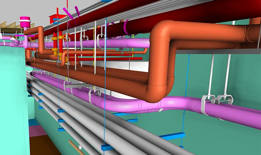
HVAC systems often occupy some of the most congested areas of a building. Large duct sections must pass through ceiling spaces, shafts, corridors, and mechanical rooms that are also used by plumbing, electrical, fire protection, structural, and architectural elements.
A route that appears workable in a two-dimensional drawing may become difficult to install once the complete building environment is considered. Structural beams, ceiling heights, cable trays, pipework, lighting systems, and access requirements can all affect the final duct layout.
HVAC BIM modeling allows these conditions to be reviewed before fabrication begins. By identifying problems earlier, the project team can make informed decisions before materials are manufactured or delivered to the site.
Fabrication-ready HVAC systems also provide more accurate information for shop production. Instead of interpreting general design geometry, the fabricator receives a coordinated model that reflects actual dimensions, fitting configurations, connection conditions, and approved routing.
What Makes an HVAC Model Fabrication-Ready?
An HVAC model becomes fabrication-ready when it contains enough verified information to support manufacturing, assembly, and installation.
The required level of detail depends on the project scope, contractor standards, fabrication method, and BIM execution plan. In many projects, fabrication-ready elements are developed to LOD 400, which is commonly associated with fabrication, assembly, and installation information.
A fabrication-ready model may include actual duct dimensions, fabrication fittings, material specifications, joint types, insulation thicknesses, equipment connections, dampers, access doors, supports, sleeves, penetrations, and service clearances.
It may also include spool numbers, piece marks, material quantities, fabrication status, and drawing references. The model should communicate not only where the system is located, but also how it will be produced and installed.
Visual detail alone does not make a model fabrication-ready. The information must be coordinated, approved, accurate, and suitable for its intended downstream use.
Step 1: Define the BIM and Fabrication Requirements
The mechanical BIM workflow should begin with clearly defined project requirements.
Before modeling starts, the contractor, BIM manager, mechanical engineer, and fabrication team should agree on the required deliverables. This includes the target level of development, coordination milestones, model responsibilities, file formats, naming standards, drawing requirements, and review procedures.
The team should also identify which HVAC elements need fabrication-level development. Not every object in the model needs to reach the same level of detail. Main duct runs, equipment connections, mechanical rooms, risers, and prefabricated assemblies may require more detailed development than secondary elements.
These expectations are often documented in a BIM execution plan or model production schedule. Establishing them early helps prevent overmodeling, inconsistent output, and disagreements about whether the model is ready for fabrication.
The fabrication team should also be involved at this stage. Their input helps ensure that the model supports the actual production methods, fitting standards, material requirements, and assembly practices that will be used.
Step 2: Collect and Validate Project Information
The accuracy of the mechanical BIM model depends on the quality of the source information.
The BIM team should review the latest mechanical design drawings, architectural model, structural model, reflected ceiling plans, equipment schedules, specifications, and available models from other MEP disciplines.
Equipment submittals are particularly important. Manufacturer dimensions, connection points, access requirements, and maintenance clearances may differ from generic design families.
For renovation and retrofit projects, field surveys or point-cloud data may be needed to verify existing conditions. Ceiling congestion, structural framing, existing ductwork, and equipment locations should not be assumed from outdated drawings.
Any missing or conflicting information should be documented through coordination comments or requests for information. Unsupported assumptions can create serious problems later in the workflow, especially after fabrication begins.
Step 3: Establish the Mechanical BIM Environment
Once the project inputs have been reviewed, the BIM team can establish the mechanical modeling environment.
The first priority is alignment. Levels, grids, shared coordinates, and building references must match the architectural and structural models. A small coordinate error can create repeated clashes and inaccurate drawing output throughout the project.
The team should also establish model organization standards. Worksets, view templates, system classifications, naming conventions, and file structures should be consistent across the project.
Approved mechanical families and fabrication content should be loaded before detailed modeling begins. These components should include accurate dimensions, connectors, parameters, and clearance requirements.
A properly configured environment improves collaboration and makes it easier to produce reliable schedules, drawings, clash reports, and fabrication data later in the process.
Step 4: Develop the HVAC Design-Intent Model
The next stage is to translate the mechanical design documents into a coordinated three-dimensional model.
The design-intent model usually includes supply air, return air, exhaust, outside air, smoke-control systems, mechanical equipment, air terminals, dampers, shafts, and risers.
The model should preserve the engineer’s intended airflow, equipment capacities, duct sizes, and system relationships. BIM modelers should not make changes that affect engineering performance without review and approval from the responsible design team.
At this stage, the focus is on accurately representing the intended system and identifying areas where the design requires further clarification.
The design-intent model becomes the foundation for coordination. It should be complete enough to review the HVAC system against architecture, structure, plumbing, electrical, and fire protection models.
Step 5: Convert the Model to Fabrication Content
A critical stage in the mechanical BIM workflow is the transition from generic design elements to fabrication-capable components.
Generic duct fittings may be suitable for engineering documentation, but they may not represent the exact fitting geometry, joint types, materials, or manufacturing standards used by the contractor.
During fabrication development, generic elements are replaced or converted into approved fabrication content. Actual elbows, transitions, offsets, connectors, reducers, access doors, dampers, and equipment connections are added according to project requirements.
Insulation and lining should also be included where they affect coordination. A duct may appear clear of another service when viewed without insulation, but the completed assembly may create a physical conflict.
The fabrication database or content library should match the contractor’s production methods. Incorrect fabrication settings can result in fittings that appear correct in the model but cannot be manufactured efficiently.
Step 6: Coordinate HVAC Systems with Other Trades
MEP coordination is one of the most important stages in producing fabrication-ready HVAC systems.
The mechanical model should be reviewed within a federated environment that includes the latest architectural, structural, plumbing, electrical, and fire protection models.
The coordination team should evaluate more than direct physical clashes. It should also consider installation access, maintenance clearances, hanger locations, ceiling heights, equipment removal paths, and construction sequencing.
For example, a duct may not physically intersect a pipe, but the spacing between them may be too small for insulation or installation tools. Similarly, a piece of equipment may fit within the mechanical room but lack sufficient space for filter replacement or future maintenance.
Successful coordination requires input from the people who understand how the systems will actually be constructed. BIM software can identify geometric conflicts, but it cannot fully evaluate fabrication and installation practicality without human review.
Step 7: Perform HVAC Clash Detection
HVAC clash detection helps teams systematically identify conflicts between mechanical systems and other building elements.
Clash tests are commonly created for HVAC against structure, architecture, plumbing, electrical, and fire protection systems. Separate tests may also be used for equipment clearances, duct insulation, access zones, and internal mechanical conflicts.
Each issue should be reviewed, assigned to the responsible team, and tracked until it is resolved. Simply moving one element away from another is not always an acceptable solution.
The revised route must still meet airflow requirements, fabrication limitations, ceiling constraints, and installation conditions. A clash resolution that creates excessive fittings or restricts maintenance access may introduce a new problem.
After revisions are completed, clash tests should be rerun using the updated models. An issue should only be considered closed after the revised condition has been reviewed and accepted.
Step 8: Complete the Constructability Review
Clash-free does not always mean construction-ready.
A detailed constructability review evaluates whether the HVAC system can be fabricated, transported, assembled, installed, accessed, and maintained.
The project team should consider the size and weight of duct assemblies, site access, lifting restrictions, door openings, corridor widths, installation sequence, and available working space.
Large duct sections may need to be divided into smaller assemblies to pass through the building. Field joints should be placed in locations where installers can safely access and complete the connection.
Mechanical room layouts require additional attention. Equipment, ductwork, piping, supports, controls, access zones, and maintenance paths must all function within a limited area.
Constructability reviews should involve mechanical contractors, fabricators, field supervisors, and experienced coordinators. Their practical knowledge helps identify problems that may not appear in automated model reviews.
Step 9: Model Supports, Penetrations, and Access Requirements
Fabrication-ready HVAC models should account for the elements that support and connect the system to the building.
Hangers, trapeze supports, inserts, sleeves, openings, and seismic bracing may need to be included or coordinated, depending on the project scope.
Support locations should be reviewed against structural elements and other MEP services. The model should also account for insulation, access panels, damper access, equipment service zones, and maintenance requirements.
Openings through walls, floors, and structural elements should be coordinated before construction. Accurate sleeve and penetration information helps structural and general-contractor teams prepare the required openings.
When these elements are ignored, the main duct route may appear coordinated while the complete installation remains unresolved.
Step 10: Divide the System into Fabrication Spools
Once the coordinated HVAC model is approved, the system can be divided into logical fabrication and installation packages.
Spool boundaries should reflect shop capabilities, transportation limits, building access, lifting capacity, installation sequence, and field conditions.
Each spool or assembly should receive a unique identification number connected to the model and drawing set. The identification system should remain consistent through fabrication, delivery, and installation.
HVAC spool drawings typically include the dimensions, fittings, materials, connection points, and piece information needed to manufacture and assemble a defined section of the system.
Well-planned spool packages can improve shop productivity and reduce the amount of cutting, measuring, and assembly required on site.
Step 11: Produce HVAC Shop Drawings
After coordination and fabrication detailing are complete, the approved model can be used to generate HVAC fabrication drawings and installation documentation.
Typical deliverables include coordinated floor plans, ductwork shop drawings, equipment connection details, mechanical room layouts, sections, elevations, riser drawings, sleeve drawings, hanger layouts, and spool drawings.
The drawings should be generated directly from the approved model wherever possible. This helps maintain consistency between model geometry, dimensions, tags, notes, and schedules.
Shop drawings should clearly communicate elevations, duct sizes, fitting locations, connection conditions, and installation requirements. Enlarged views and sections should be used in congested areas where standard plans do not provide enough information.
Before release, the drawing set should be checked against the current model revision and coordination status.
Step 12: Perform Quality Control
Quality control should be integrated throughout the mechanical BIM workflow rather than treated as a final activity.
The model should be reviewed for duct dimensions, elevations, fitting geometry, equipment locations, connector alignment, insulation thickness, access requirements, and support conditions.
The project team should also verify system names, materials, service classifications, equipment tags, spool numbers, drawing references, and required parameters.
Coordination status must be reviewed before fabrication release. Open clashes, unresolved RFIs, outdated linked models, or unapproved routing changes should be clearly identified.
The drawing review should confirm dimensions, notes, tags, sections, details, revisions, and material schedules. Independent checking is valuable because a model can appear visually complete while still containing incorrect or incomplete information.
Step 13: Control Revisions and Fabrication Releases
Revision control becomes especially important once fabrication begins.
The project team should maintain a clear record of which model version is approved, which shop drawings are released, and which areas remain under coordination.
Fabricators and installers should have access to the latest approved information. Superseded drawings should be removed from active use to reduce the risk of construction from outdated documents.
A model change that appears minor may affect completed spools, ordered materials, supports, sleeves, equipment connections, and installation sequencing. For this reason, revisions should be reviewed for downstream impacts before they are approved.
Release packages should clearly identify the relevant model version, drawing revision, fabrication status, and unresolved conditions.
Step 14: Support Field Installation and As-Built Updates
The mechanical BIM workflow should continue during construction.
Field teams can use coordinated models and drawings to review installation locations, elevations, sequence, equipment connections, and access conditions.
When field conditions differ from the approved model, the changes should be documented and communicated to the BIM team. This helps maintain alignment between the model and the installed system.
Approved field changes can then be incorporated into the as-built model. Depending on the project requirements, the final model may include verified routing, equipment data, asset information, maintenance access, and links to operations documentation.
A properly updated as-built model provides more value than a design model that no longer reflects the installed building.
Common Mechanical BIM Workflow Challenges
One common mistake is treating a design model as if it were ready for fabrication. Design geometry may communicate the intended system but lack the fittings, materials, joints, supports, and assembly information required for shop production.
Another challenge is beginning detailed modeling before the deliverables are defined. Without clear requirements, teams may spend time developing unnecessary content while missing important fabrication information.
Poor coordination between the BIM team and fabrication team can also create inconsistencies. The model may use components or fitting configurations that do not match the contractor’s actual manufacturing process.
Version-control problems are equally serious. Fabrication from outdated drawings can lead to wasted materials, rework, and installation delays.
Overmodeling should also be avoided. The objective is to develop the information required for coordination, fabrication, and installation, not to create unnecessary detail that slows model performance without adding construction value.
Benefits of a Fabrication-Ready Mechanical BIM Workflow
A coordinated mechanical BIM workflow improves the reliability of HVAC fabrication by giving production teams access to verified dimensions, approved routing, and accurate fitting information.
It also improves multidisciplinary coordination by allowing HVAC systems to be reviewed in relation to structural, architectural, plumbing, electrical, and fire protection elements.
Prefabrication planning becomes more effective because coordinated systems can be divided into controlled production and installation packages. Material takeoffs, spool drawings, and shop schedules can be generated from a consistent source of information.
Field installation teams also receive clearer documentation. Coordinated plans, sections, elevations, and model views help reduce uncertainty during construction.
Most importantly, the workflow connects design, coordination, fabrication, and installation. This reduces the information gaps that often occur when each stage is managed independently.
Choosing a Mechanical BIM Services Partner
A mechanical BIM services provider should understand both modeling technology and HVAC construction.
Software knowledge alone is not enough. The provider should understand mechanical systems, duct fabrication, fitting requirements, equipment access, support coordination, and installation sequencing.
Experience with LOD 400 HVAC modeling, MEP coordination, ductwork shop drawings, digital prefabrication, HVAC spool drawings, and mechanical room modeling is particularly valuable.
The provider should also follow a defined quality-control process and maintain clear communication throughout coordination and revision cycles.
A dependable BIM partner should be able to explain how the project will move from engineering documents to coordinated, approved, and fabrication-ready deliverables.
Develop Fabrication-Ready HVAC Systems with Endeion
A fabrication-ready HVAC model is not created by adding detail without purpose. It is developed through a controlled mechanical BIM workflow that connects engineering intent, coordination, constructability, fabrication requirements, and quality assurance.
Endeion supports contractors, engineering firms, fabricators, and VDC teams with mechanical BIM services, HVAC BIM modeling, MEP coordination, LOD 400 fabrication modeling, ductwork shop drawings, HVAC spool drawings, and mechanical room modeling.
By developing coordinated and construction-focused deliverables, project teams can improve fabrication planning, reduce field uncertainty, and support more efficient HVAC installation.
Contact Endeion to discuss mechanical BIM support for your next HVAC fabrication or coordination project.
FAQs
What is a mechanical BIM workflow?
A mechanical BIM workflow is the process used to develop HVAC systems from engineering design information into coordinated models, fabrication drawings, spool packages, and installation documentation. It includes model setup, HVAC BIM modeling, clash detection, constructability review, fabrication detailing, quality control, and revision management.
What is a fabrication-ready HVAC model?
A fabrication-ready HVAC model contains the verified geometry and information needed to manufacture, assemble, and install mechanical components. It may include actual fittings, materials, connectors, insulation, equipment details, supports, penetrations, spool divisions, clearances, and fabrication parameters.
What is the difference between LOD 350 and LOD 400 HVAC modeling?
LOD 350 HVAC modeling is generally used for detailed construction coordination, including relationships with surrounding systems. LOD 400 HVAC modeling includes additional information required for fabrication, assembly, and installation. The exact requirement should be defined in the project BIM execution plan.
How does HVAC clash detection improve fabrication?
HVAC clash detection helps identify conflicts between ductwork, equipment, structure, architecture, plumbing, electrical, and fire protection systems before fabrication begins. Resolving these issues early reduces the likelihood of producing components that cannot be installed as planned.
What information is included in HVAC shop drawings?
HVAC shop drawings commonly include duct sizes, elevations, dimensions, fitting locations, equipment connections, sections, details, access requirements, and installation notes. They may also include sleeve layouts, hanger information, risers, and mechanical room arrangements.
What is the difference between HVAC shop drawings and spool drawings?
HVAC shop drawings show the overall coordinated system and its installation requirements. Spool drawings focus on individual prefabricated sections or assemblies. They usually include piece marks, fittings, dimensions, materials, joints, and connection details needed for production.
Can BIM support HVAC material takeoffs?
Yes. When the model contains accurate components, dimensions, materials, and parameters, it can support HVAC material takeoffs and procurement planning. The output should still be reviewed against project specifications, fabrication standards, and current model revisions.
Why is constructability review necessary after clash detection?
Clash detection identifies geometric conflicts, but it does not always confirm whether the system can be fabricated or installed. Constructability review considers access, lifting, transportation, assembly space, maintenance requirements, field joints, tools, and installation sequencing.